SX-Control – SEM More
Overview
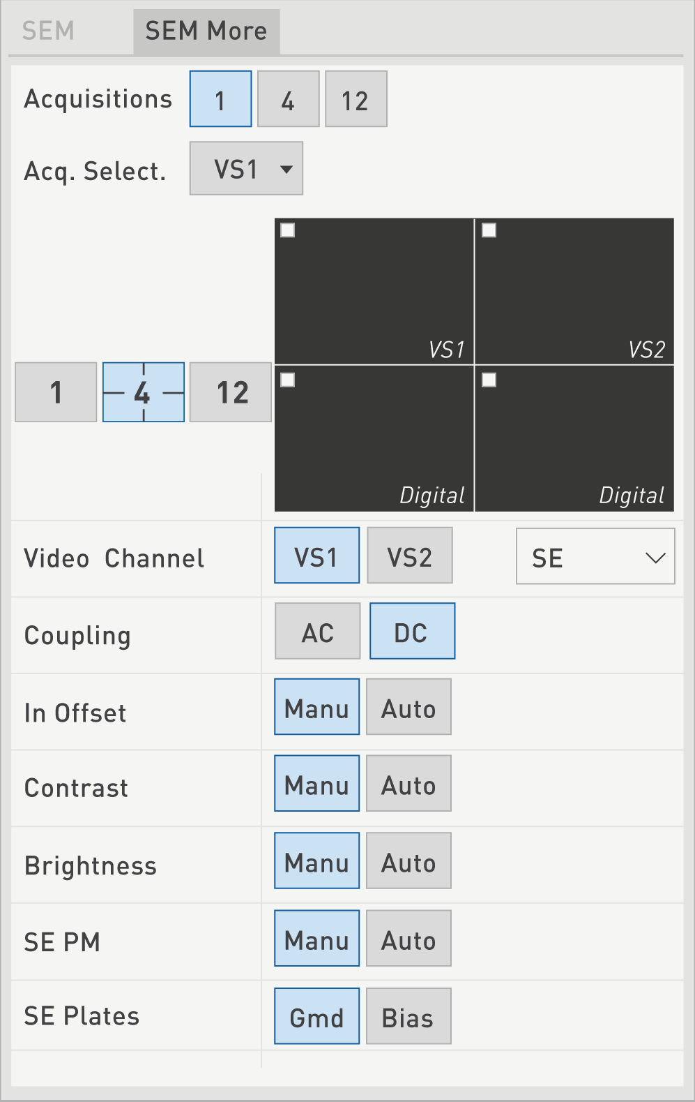
A few advanced settings are available for a more in-depth treatment of the images acquired during an EPMA experiment. These settings are accessible under the SEM More menu.
Display
The ‘Rotation’ option indicates the value of the electronic rotation applied on the displayed image. The rotation is in degrees and is adjusted by using the dedicated physical thumbwheel of the Control Keyboard. One can Reset the rotation value to 0, or Set a Rotation Offset to compensate for the mechanical misalignment of the scanning device with the X axis. An angle rotation or offset is adjusted to have a coincidence between the horizontal beam scanning and the horizontal stage motion.
The ‘Reset’ option allows users to reset individual parameters such as the Probe Marker, the Image Shift or the Rotation discussed above. The Probe Marker shift is used to correct any misalignment between the beam impact and the crosshair of the optical image.
Instead of moving the stage, one can displace the image of the RTM by using the Image Shift function, with the Shift X and Shift Y thumbwheels.
Video Channel
Same as for SEM sub-panel
Contrast, Brightness and In Offset
The Contrast, Offset, and Brightness parameters can be tuned to control the Video signals [VS1 and VS2].
The Contrast function controls the gain of the Video amplifier. It can be set in either Manual or Automatic mode. The Brightness function controls the output Offset of the Video amplifier. The Brightness can also be set in either Manual or Automatic mode.
The In Offset option controls the input Offset of the Video Amplifier, and the larger the In Offset value, the Brighter the image. Manual and Automatic modes are once again available.
The numerical values for the Contrast, Brightness and In Offset parameters are visible from the Stage/Roller panel, part of the fifth menu of the SX Control module.
Each parameter value can go from 0 to 1023 (unit-less), but for BSE are generally set around 600 for Brightness and 400 for In Offset.
Coupling
To get the AC and DC components of the Video signals, Coupling has to be made between the detector and the amplifier, either directly for DC, or through a capacitor for AC. Although DC coupling can be used for all kinds of images, this setup is mandatory for images acquired at low scanning speeds. The AC mode is generally reserved for acquiring images at very intense beam currents.
Only for SE display
The Photo-Multiplier (PM) can be set to ‘Manual’ or ‘Auto’.
The Auto mode is useful if one navigates on the sample as a reconnaissance step to find a feature. Otherwise, the preferred mode is the Manual mode as it acts as a brightness control knob adjusting the signal from the PM.
In order to ascertain that the collected Secondary Electrons are collimated, the scintillator is preceded with Plates on the optical path. These Plates can be turned OFF to minimize the SE collection when an intense primary beam current is used.
Only for BSE display
The BSE DC/AC can be set to ‘Auto’ or ‘Off’.
The ‘Auto’ mode defines automatically brightness, contrast, offset and gamma. This mode is recommended in case of highly-chemical heterogeneous samples. Otherwise, the preferred mode is the Manual mode as it acts as a brightness or contrast control knob adjusting the signal from BSE detector.
The BSE Polarizer can be set according ground (‘Grnd’) or ‘Bias’.
Only for BSE HQ display
The ‘Auto’ mode defines automatically brightness and contrast. This mode is recommended in case of highly-chemical heterogeneous samples.Otherwise, the preferred mode is the Manual mode as it acts as a brightness or contrast control knob adjusting the signal from BSE HQ detector.
The BSE detector can be turned Off or On and the user can adjust automatically or reset the contrast and brightness by clicking on the Adjust/Reset button.
Related Article
SX-Control – Source
Reading Duration 1min
This tab is only dedicated to the SX system including the Field Emission Gun (FEG).
SX-Control – SEM
Reading Duration 10min
Once the beam setup parameters are properly defined and the vacuum levels are good enough to start an analysis, aspects related to the Scanning Electron Microscope as well as the Wavelength Dispersive Spectrometers (WDS) panel need to be considered. In this section, users will have control of the parameters inherent to the video signals coming through the Video Channels and displayed on the RTM.
SX-Control – Camera-SEM
Reading Duration 8min
The upper right panel of the SX-Control module is the Camera panel and controls parameters linked to the optical light microscope. This latter can be operated using transmitted or reflected light, in normal or polarized mode, and at various magnifications and Z focus settings.
SX-Control – WDS panel
Reading Duration 2min
The fourth menu of the SX Control module controls the spectrometry part of the instrument (definition of the WDS parameters).
Contact

Our support team is ready to help you
FAQ

Answers to some common questions from SX users
Troubleshooting

Quickly search for solutions to instrument issues