SX-Control – Multipurpose
Overview
The last panel available in the SX Control menu is the last one, and has been partially covered in the other sections of the SX Control. This panel serves multiple purposes for the user.
While some of the tabs in this panel are used in conjunction with the other SX- Control panels, such as Vacuum , Beam and WDS , other functionalities such as those pertaining to the Stage, the Specimen and the Sample Navigator can only be accessed from this panel.
![]()
Vacuum Synoptic
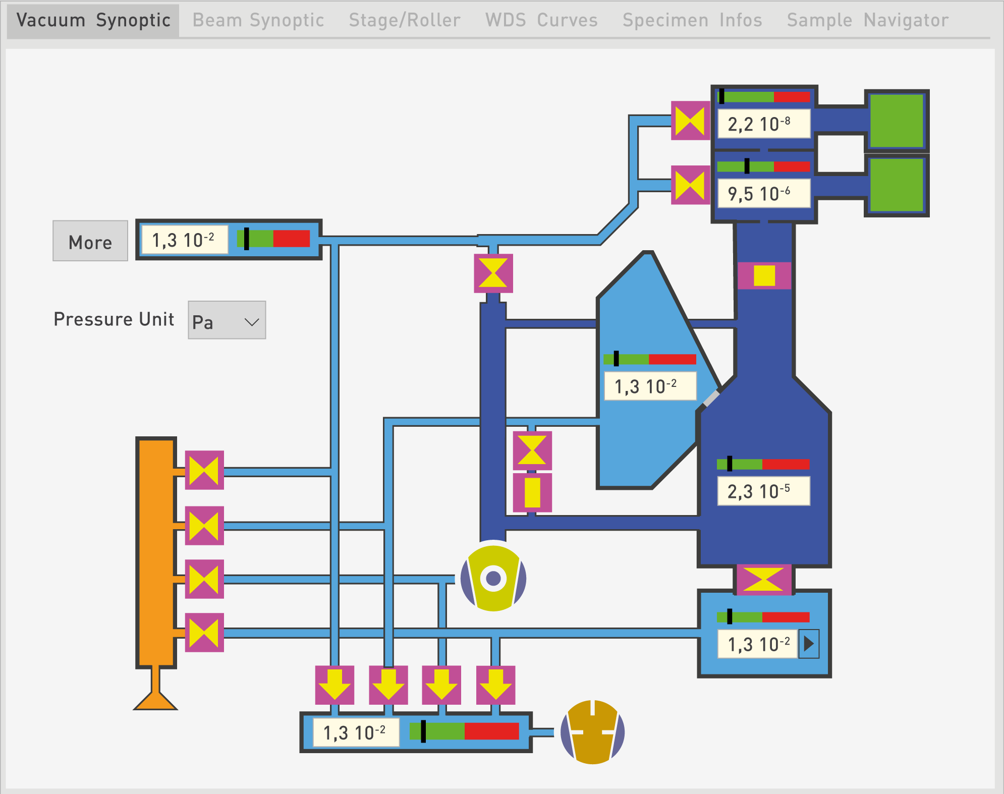
By clicking on the Vacuum Synoptic tab, the live vacuum readings are indicated for each vacuum compartment of the instrument, as well as the status of the pumps and valves.
All the major components of the vacuum system such as primary pump (PP), electro-pneumatic gate valves (EP), turbo-molecular pumps (TP), and ion pump (IP) are displayed along with their running regimes (sliders) or open/close status.
When the sliders are within the green regions, this indicates that all pressures are in the correct range for the system to safely operate. When the sliders are within the red regions, the vacuum levels are faulty or not good enough and above the authorized thresholds for safely operating the EPMA system.
By default, when the Vacuum Synoptic tab is activated, only the simplified version of the schematic is shown, as illustrated above in Fig. a. The only information accessible are the vacuum readings in the Pressure Unit that has been selected (Pa, Torr or mBar). Since this panel is interacting with the main SX-Control Vacuum panel, any pressure unit selection in one panel will automatically be reflected in the other one. A full version of the Vacuum Synoptic is available by clicking on the ‘More’ button, and the resulting diagram is shown in Fig. a. The ‘More’ button will then turn into a ‘Less’ button, allowing users to revert to the simplified schematic.
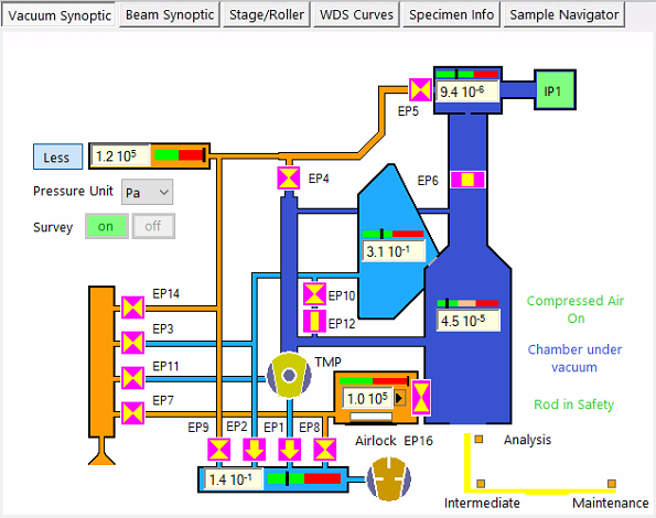
Skaphia (shielded version) has a different vacuum synoptic as displayed below. The sample holder is transferred manually through the analysis chamber (and EP16 valve between the airlock and the chamber is controlled by the user in SX Control panel).
By clicking on the Beam Synoptic tab, two parts can be displayed: the left part which shows a schematic of the beam passing through the beam components, and the right part called the Roller, displaying all the numerical values associated with the current beam characteristics.
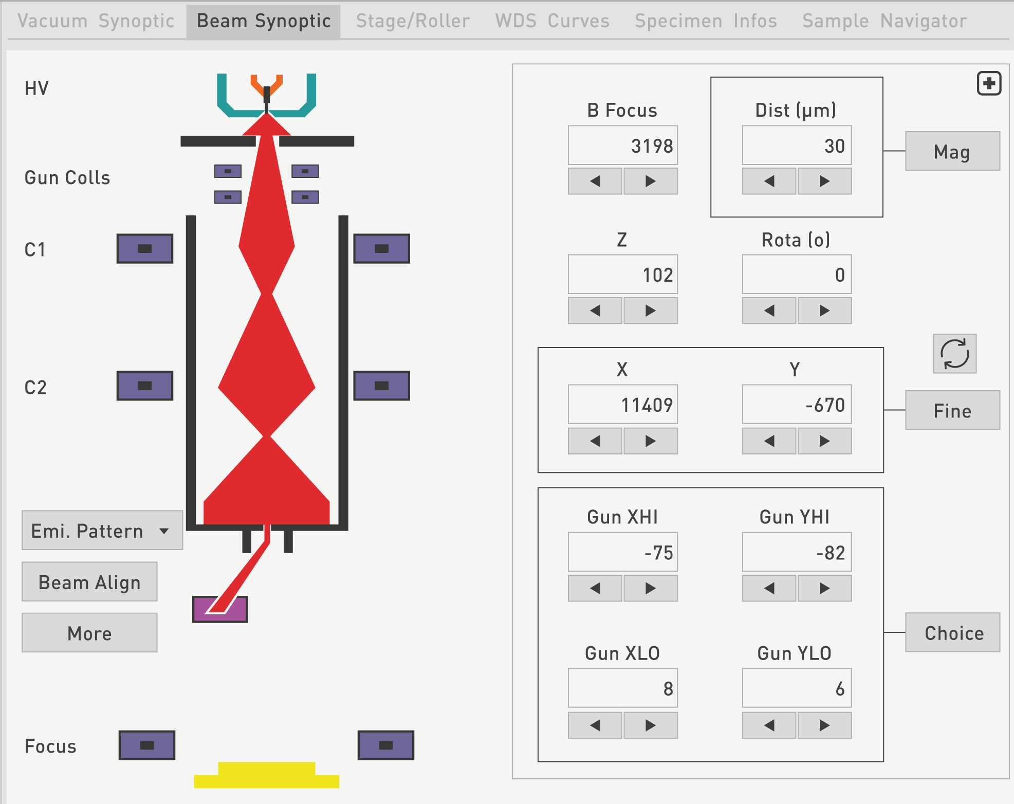
A corresponding reading is available with each of the beam parameters needed to align the electron beam column. As for the Vacuum Synoptic panel, by clicking on the ‘Less’ button, only the beam path is displayed without the associated numerical values.
A positive High Voltage is applied on the Extractor electrode (2.5 to 3 kV typically) with respect to the tip. Under this high electrical field, electrons are emitted by the sharp end of the tip. The Extractor current (µA) corresponds to the tip emission current and the HV current (µA) refers to the beam current delivered by the source. As some thermal electrons are emitted by a thermo-electronic effect, an electrode called the Suppressor electrode is biased with a negative voltage (300 V typically) with respect to the tip in order to remove these electrons.
The Extractor aperture (100 µm in diameter) reduces the effective size of the electron source. The electrons are then focused with an Einzel lens positively biased with respect to the filament.
The entire source is biased with respect to the ground potential (specimen) by the accelerating voltage. The current measured by the HV power supply consists of the electron beam current delivered by the FE source. The final beam current is adjusted by varying the condenser lens inside the column.
When the electron beam is turned ‘On’ in the SX-Control Beam panel , the software automatically heats the filament to a preset value, brings the Suppressor voltage to 300 V, conditions the Einzel Lens (El) voltage and the Accelerating voltage to the last used values, and sets the Extractor voltage to its nominal value.
The nominal values used by this routine are characteristic of the installed Field Emission module, and are entered in the SX-Control Source Parameters sub-panel .
For SX-FIVE equipped with W and LaB6 sources, dedicated synoptics are displayed only with the revelent information's as shown below.
When the electron beam is turned ‘Off’ in the SX-Control Beam panel , the routine automatically sets the Accelerating voltage, Extraction voltage, and Heating current to zero.
The Emission Pattern function on the Beam Synoptic can be used to scan the top coils or the bottom coils in the column.
Finally, at the bottom of the Beam Synoptic, the Beam Focus value is displayed where the electron beam impacts the specimen.
The Beam Roller section on the right hand side of the Beam Synoptic tab can be expanded by clicking on the ‘+’ button as a free window.
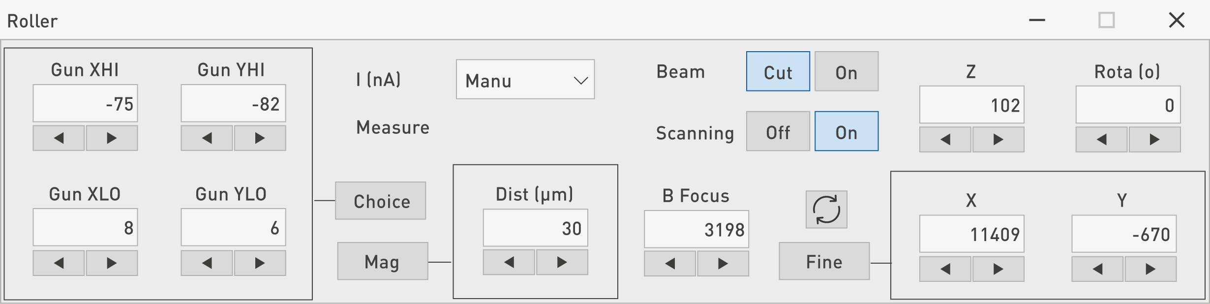
Once all parameters are set to the users’ preference, this Roller panel can be shrunk by clicking on ‘x’.
All the parameters and associated drop down options have already been described and discussed in the SX-Control Beam and Source sub-panels.
Roller Tactis

In case of SX5-Tactis, the roller panel is available in the beam synoptic and stage/roller sections.
The third tab in the multi-purpose window of the SX Control program concerns the Stage/Roller.
Each parameters can be tuned by the Shuttle Express® using the main roller or finely tuned using the small roller in the middle of the mouse.
The user has to put the mouse on the desired parameters to adjust the value.
Do not click on the parameter (otherwise the parameter will change but the new value won’t be display) , only position the mouse on the parameter.

The Beam Synoptic and Stage/Roller tabs share the right hand side of their respective windows as illustrated on the associated figure above.
Upon opening the Stage/Roller tab, the left hand side of the main window displays a schematic of the holder that is currently selected. In the specific case shown in the figure below, a 6-hole holder (also called “HO6”) is shown along with red spots and crosses of various colors and their respective meaning.
A drop down menu is available from the Holder option to select the type of holder that is present in the analysis chamber. Holders delivered with the instrument can vary from one main block up to six blocks. In the case of the HO6, six holes of 1” diameter can each be filled with a sample block. Users do have the ability to create their own holders if they wish to do so by using the “Create Holder” function in the SX Utilities/Configuration menu.
As shown below, most of the sample holders are preset in PeakSight and available through the ‘Holder’ drop-down menu. The arrangement of the blocks can be seen depending on the holders. These blocks appear in black by default but once a specimen is installed in the holder, a schematic of the block is overlaid on the holder image and is displayed with a gray background, as shown for holders HOTS2+2 and HO6.

The HOTS2+2 holder can contain two thin sections and two blocks of 1” diameter each, while the HO2+2 holder can fit two sample blocks of 1” diameter each as well as two sample blocks of 1” ach.
The HO2_User configuration illustrates a user-defined holder configuration (i.e., not part of the standard fleet of holders).
Once a holder has been chosen, a specific location listed on this holder could be selected by clicking on the option named ‘Move to Specimen’.
The resulting window shown below provides some choices in terms of the Block to select and the Sample Type, whether it pertains to a standard or reference material, or to an actual (bulk) sample that needs to be analyzed. If the Sample Type is listed as Standard, then by clicking on ’Std Wt%’, the elemental composition in weight % will be displayed. However, for a Bulk sample, this function will be unavailable, as this is the information being sought.
Finally, the update function allows users to update any information that has changed on the available list, such as name, position, or composition.
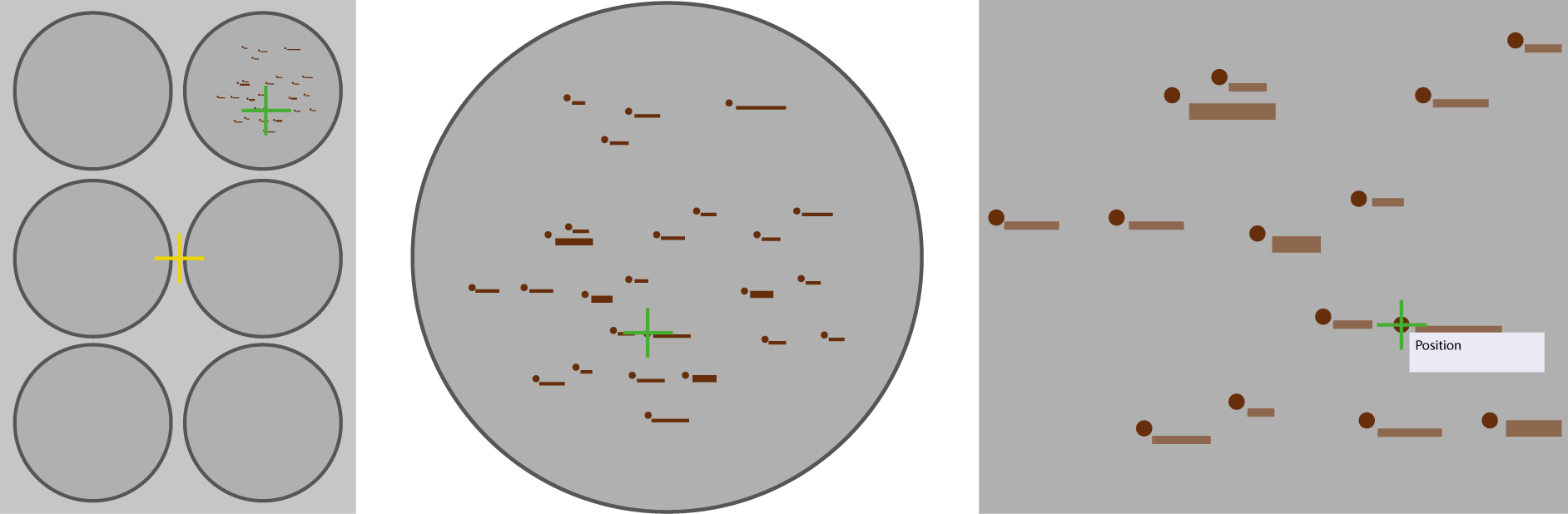
As an example, on a six-place holder (HO6) schematic, one block is active and shown in gray while five blocks remain free. It’s important to notice that each specimen position is represented by a red dot, corresponding to its actual physical location. If the image is zoomed in, the labels associated to the red dots will become visible.

When single clicking on any holder position, the sample stage indicates the corresponding coordinates that are marked by the green cross, also known as the Navigator cross. A double click will move the sample stage to the corresponding coordinates and the green cross will be at the same position as the red cross, called the Stage position.
The yellow cross is a marker that locates a standard or reference position on the selected holder.
Note: the blue dot in the middle of the yellow cross indicates that the electron beam is located on a reference sample. Both blue dot and yellow cross are shown at the center of the stage on the example.
A right click anywhere on the holder schematic will give access to a menu with various options. The first option is called Z Focus and activates the Z Auto-focus routine at the current sample stage position, by using a left click on that function.
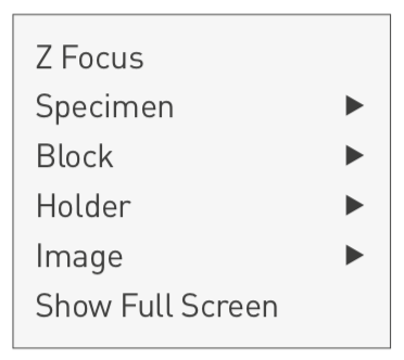
`
Once this menu is open, right click and/or left click have the same effect.
The ‘Move to Stored Position’ function allows the movement of the sample stage to the coordinates indicated by the mouse click. If this click is in the vicinity of a stored specimen location, the stage will be driven to the stored specimen coordinates corresponding to this location.
The ‘Select and Move to’ function serves the exact same purpose as the ‘Move to Specimen’ button.
In addition to the functions detailed for the “Labels” window, additional functions are available when defining a block. A user can create a new block by selecting New at Stage, Delete a block, Update its position and information, apply a Z auto Focus, Move to any existing block, or Close the window.
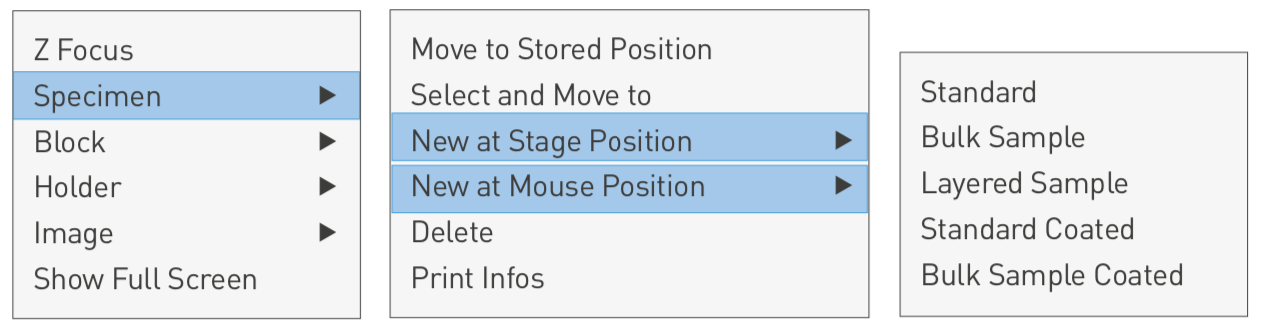
Both the New at Stage Position and New at Mouse Position functions enable users to define and store new specimens where the red and the green crosses are positioned, respectively. The same list of sample types is available, from as simple as a standard or a bulk sample, to as specific as Layered or Coated samples.
Users can also remove a sample by clicking on Delete or gather more information on it by clicking on Print Infos.
Once a Block is selected, the Show option will provide a close up of the block onto which the Navigator (green) cross is positioned. This will allow the sample names to be clearly displayed and visible, along with their positions characterized by red dots.

With the Install function, users can select an existing block from a pop-up list and assign it to the current stage position, or create a new block at this location by clicking on ’New Block’.
The dimensions of the new block are automatically matched to the block where the Navigator cross is positioned.
When a block is installed, the block location on the Holder schematic is filled with a gray background. A currently-installed block can be replaced by a block of similar dimensions by using the Install function as well.
When a block needs to be removed but not replaced, the user can select the Remove function.
Since the specimen height with respect to the electron beam is one of the critical parameters in obtaining optimal results in EPMA, it is recommended to proceed to a Z focus on a newly installed block and to then apply the Update All Z function to reflect this adjustment. The Z Auto focus routine is performed on a specimen in the block and the difference in height between the stored value and the measured value (on the order of µm) will be applied to all the specimens within that block.Under the Specimen menu, the Print Infos in the Block menu enables users to gather and print the information (name and composition) corresponding to the selected specimens of that block.
Under the Stage/Roller tab, the Holder global view is displayed by default. Since it corresponds to the Show function in the Holder menu, this function is only useful if another option was selected and one wanted to have a large field image of the selected holder.

Similarly, the shortcut to the Holder Install function was previously described under the Stage/Roller tab where the desired holder can be selected in the Holder drop-down menu.
Note: to load a holder through the Install option, the holder must be created prior to the Install routine. The selected holder will be displayed in-lieu of the previously installed holder.
The reference position is set by default to the (x, y, z) coordinates of (0,0,0). By clicking on Move to Reference, the sample stage is then placed at the (0,0,0) position.
Clicking on Update Reference will force the current stage coordinates to become the new (0,0,0) or Reference position.
The first item available in the Image menu concerns the Reset Digital Zoom. A global view of the holder and the blocks is provided at first when opening the Stage/Roller panel, but very often, it is necessary to zoom in on the locations or regions of interest in the blocks to precisely set up an experiment.

Once all the adjustments have been done by the users in the close up view, a simplified global view of the holder is obtained by using the Reset Digital Zoom from the Image menu.
The Print option will print the image displayed under the Stage/Roller tab. For instance, upon clicking Print on the close-up image, this image would be printed out on a full page with information such as its name, the date and time, some comments including the holder name and the associated block name.
On the Markers drop down menu embedded in the Images option of the Stage/Roller, three choices can be selected or deselected. The Stage Position will display or remove the red cross corresponding to the current stage position. The Beam position will display or remove the blue dot indicating the current beam position. And finally, the Stage Reference will display or remove the yellow cross associated with the center position (0,0,0).
The last option of the list available from the Stage/Roller panel is called Show Full Screen. This function can be toggled on and off. If activated, it will display the same view as shown above but in full screen (i.e., the selected holder will be zoomed in, allowing one to comfortably navigate and see every block in detail, including specimen names and actual coordinates (X, Y) on the holder). An alternative way to achieve a close up on a region of interest is to use Shift + left click and drag.
When clicking on the WDS Curves tab, the underlying window will either display the Spectrum range selected or the PHA curves for the spectrometers that have been chosen in the SX Control WDS menu. In the same window, curves can then be displayed from one to five spectrometers.
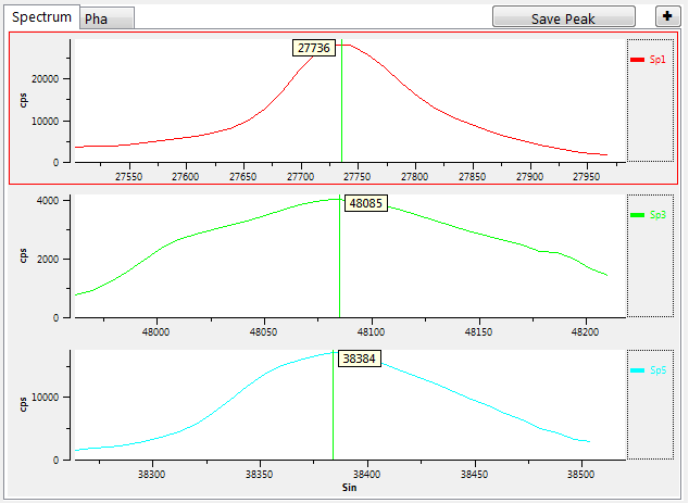
In this example, only two spectrometers (Sp1 and Sp2) were selected in SX Control WDS and therefore the WDS spectra displayed were only for these two spectrometers. The Test and Adjust PHA functions will also be active and their results will be shown for Sp1 and Sp2. For a magnified view of these curves, one can click on ‘+’ button.
Specimen Infos
A full menu dedicated to the definition of samples is found under the Specimen Infos tab. Once this tab is selected, a Label Actions menu bar is automatically launched and five main operations are possible. Users may choose to Open the existing list of blocks from which each block will display sample names, their respective (X, Y, Z) stored coordinates, and their Type, i.e., whether they are standards with known composition or bulk samples which would need to be quantified. In this particular case, by double clicking on the highlighted blue line, the detailed information regarding the specimen is displayed in the window. On the left hand side, name, type, comment, block, and X,Y,Z positions are listed, and one can Update the Position or Move Here. On the right hand side, information on Standard Composition can be found and/or edited, especially through the selection of the elements on the periodic table, their respective Wt% or At%, and their valence number.
Users have the ability to create New samples, whether they want to add a standard to their database for calibration or bulk samples for quantification. Once satisfied with the information entered, users must click on Save. If a sample was removed from the database, or erroneously logged in, a Delete option is also available. Finally, one can click on Print Composition to keep a hard copy record of the quantitative information pertaining to any sample.
Peaksight 6.2 offers a new way to navigate within a sample holder by using real pictures of the sample holder instead of schematics.
This function allows very precise motion and a real agin during the sample exploration travelling directly to the desired target.

The sample navigator needs the sample holder picture properly resized close to the limits of the sample holder and centered around the engraved cross of the standard SX sample holders.
The picture has to be loaded via the ‘Open File’ icon close to the sample holder name and calibrated through the ‘Calibrate’ button.
In calibration mode, the X and Y values for the stage and the reference image have to be define for three selected points. When it’s done, just click on ‘OK’ and the new calibrated image will acts as the sample holder scheme available at the Stage/Roller tab.
Related Article
SX-Control – WDS & Spectro
Reading Duration 45min
This section gathers all the functions and information dedicated to the Wavelenght Dispersive Spectroscopy (WDS) settings and analysis parameters.
SX-Control – Fast Acquisition
Reading Duration 11min
The Fast Acquisition frame (WDS #3) quickly gathers some measurements with the already-optimized preset values for the parameters discussed in the previous section. The four main functionalities that will be described in this Fast Acquisition frame are WDS Spectrum, Profiles, Images, and Quanti.
Contact

Our support team is ready to help you
FAQ

Answers to some common questions from SX users
Troubleshooting

Quickly search for solutions to instrument issues